Piranha Offroad Alternator Output Compensator

The Piranha Offroad Alternator Output Compensator AOC makes using a DC/DC isolator for dual battery management a thing of the past, for many vehicles.

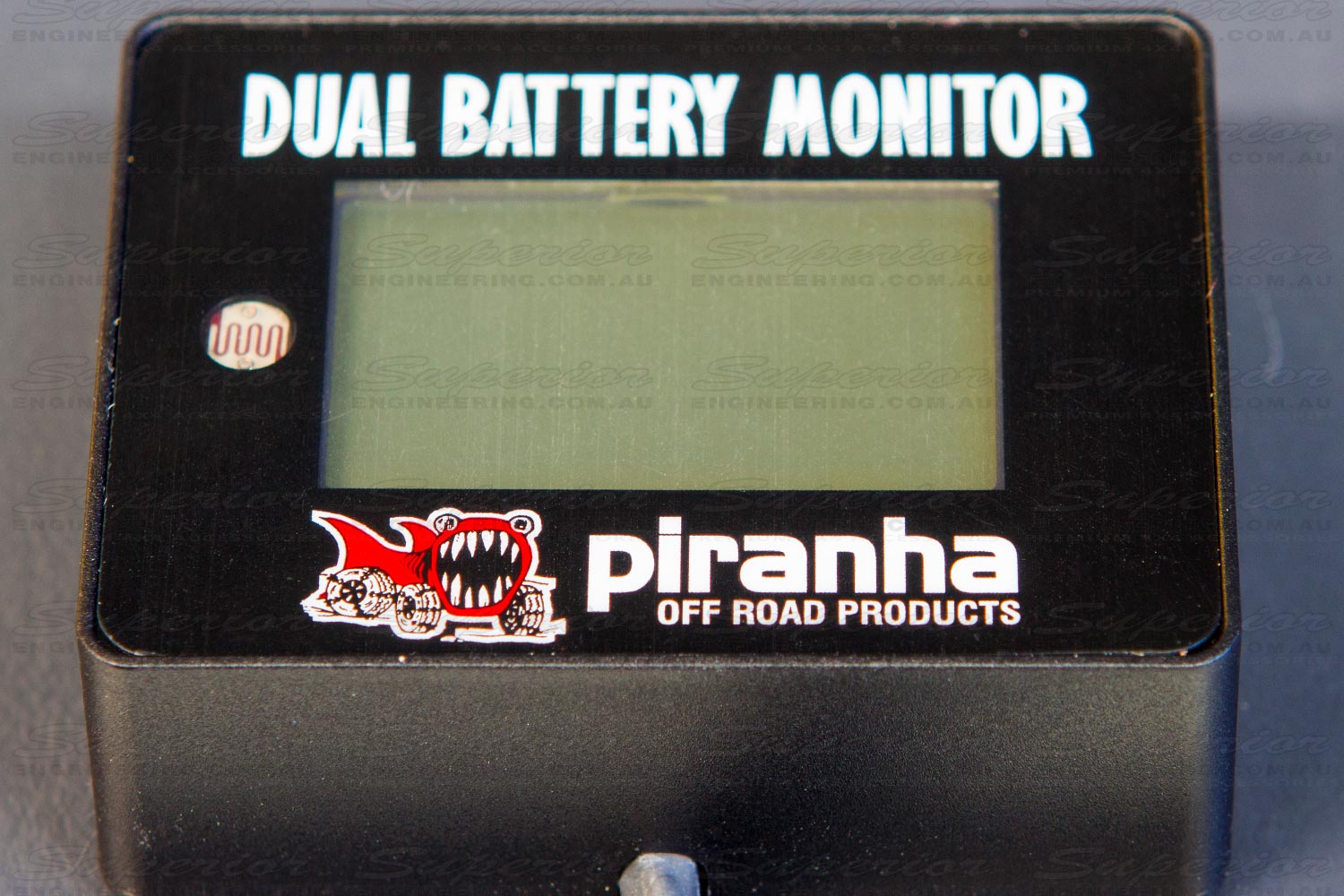
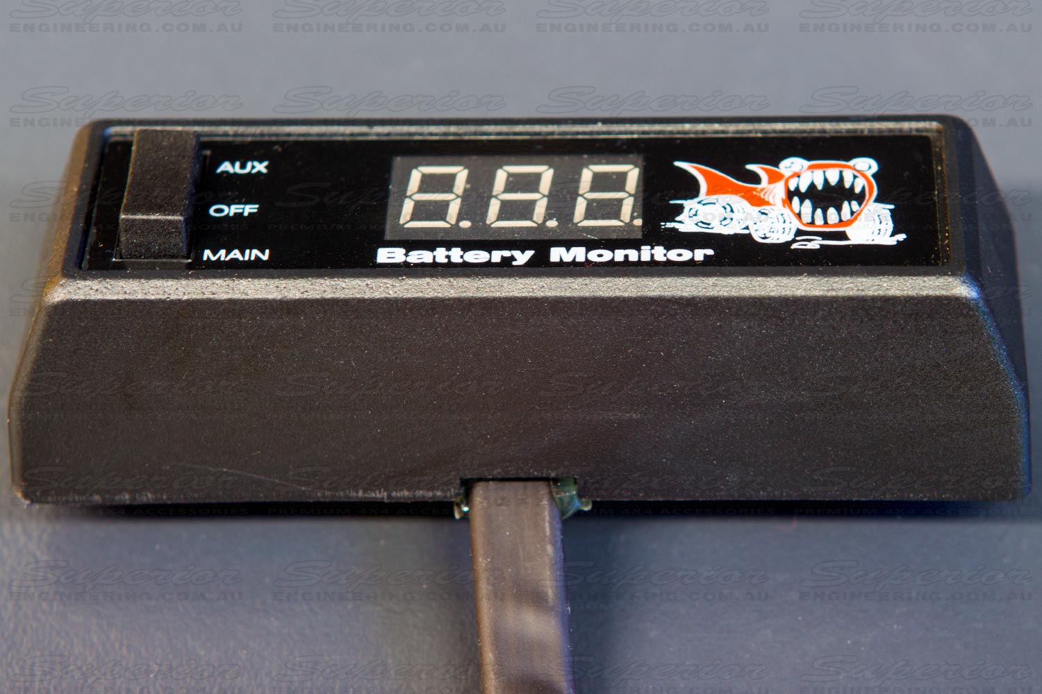
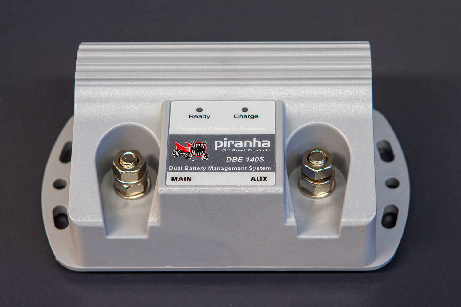
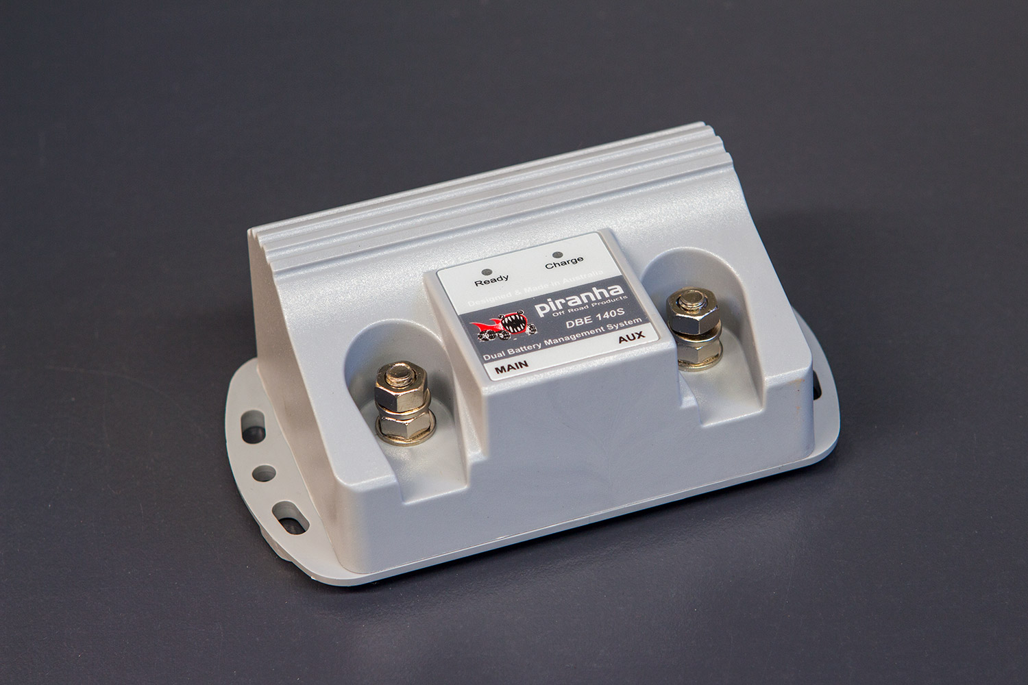
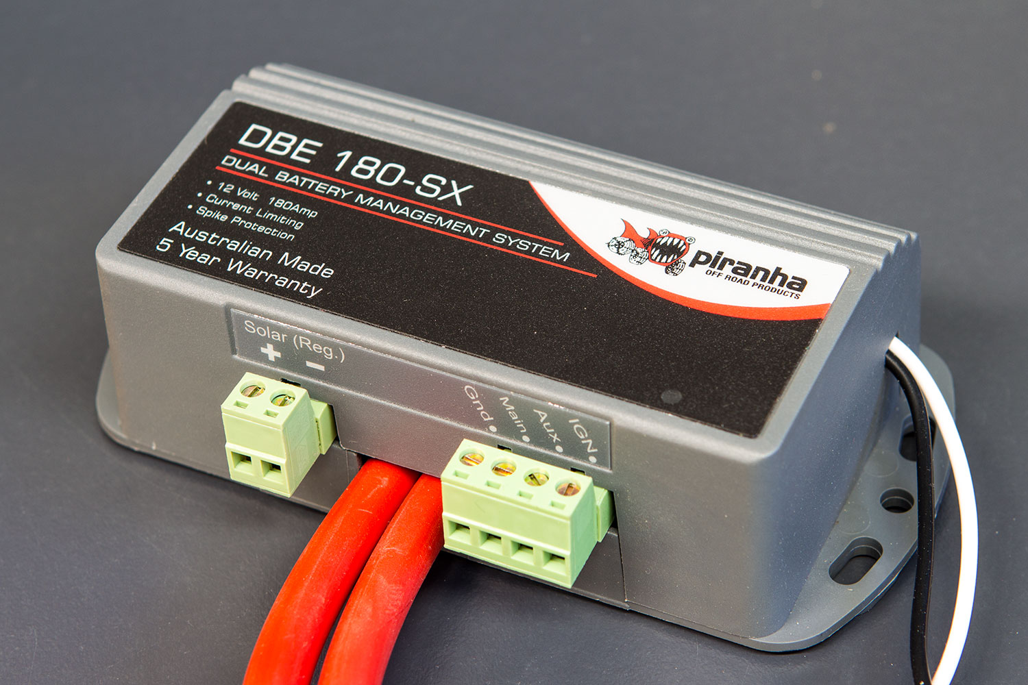
Using the Piranha AOC in conjunction with a Piranha Dual Battery manager, DBE140S or DBE180-SX, allows you to use the full available output of the alternator to recharge your auxiliary battery / batteries while the vehicle is in use.

It will also charge your main battery if you have changed to a high technology AGM style battery.

The AOC is designed for use with many of today’s current 4×4 vehicles with VARIABLE RATE ALTERNATORS which up to now used a DC/DC style isolator, which is a high cost solution and limited to the output of the DC/DC. Most times slowing down the recharge time.

For such a small device it packs a very capable electronics package to provide a very useful .4Volt -.5Volt increase in your charge rate while still affording all the protection of a fused circuit as required by the manufacturer.

There are similar looking devices available that do not offer the fused protection of the Piranha AOC and are only one way.

Research and engineering have combined to provide this low cost, high technology solution, suitable for today’s vehicles.

Side View of the Piranha Offroad Alternator Output Compensator Kit

Front View of the Piranha Offroad Alternator Output Compensator Kit & Packet

Suitable for the following four wheel drive vehicles:

  • Toyota Prado 120 Series
  • Toyota Prado 150 Series
  • Toyota Hilux 2005 Onwards
  • Toyota Landcruiser 200 Series
  • Toyota Landcruiser 79 Series
  • Toyota Landcruiser 79 Series with V8 Diesel
  • Will suit other vehicles with ALT Sense wire, ALT S fuse, without a CANBUS system.

Buy Online

AOC Fitting Guide

MAKES DC/DC

A Thing Of The Past!

AOC

ALTERNATOR OUTPUT COMPENSATOR

Full output from your variable rate alternator.

Allows installation of:

AGM Starting Battery

and / or

Dual Battery System

On many vehicles with variable rate alternators.

AOC & Fitting Instructions Enclosed.

FITTING INSTRUCTIONS

You will require a digital multi-meter.

  1. With the vehicle running use the multi-meter to establish alternator output at Main Battery, if already 14.5 Volts+, AOC not required.
    1. WARNING: Do not use AOC if measured voltage at main battery is above 14.5V.
  2. Now switch vehicle OFF and make sure ignition is OFF.
  3. Locate fuse box under bonnet.
  4. Remove the small ALT S fuse, usually 7.5 amp or 5 amp.
  5. Refit the Piranha AOC.
  6. Start vehicle and retest with multi-meter, should read 0.4V-0.5V higher than first reading.

WARNING

If there is an overload or short circuit in the alternator sense cable the AOC is designed to fail, this is not covered by warranty.

The reseller or manufacturer cannot be held responsible for any failures or subsequent events as a result of using this product.

This is a modification to your vehicle and is undertaken at your own risk. Consult your owners manual or vehicle warranty information before making any modifications.

Modifications may affect vehicle manufacturers warranty conditions.

AOC

BOOSTS ALTERNATOR OUTPUT BY UP TO 0.5 VOLT

The AOC used in conjunction with a Piranha Dual Battery Manager (DBE140 & DBE180-SX) provides a technically superior solution to charging your auxiliary battery, at a fraction of the cost of using DC/DC step up chargers.

Download Fitting Guide

Simple to use, low cost, safe, with full vehicle protection.

Piranha Offroad Battery Monitors

Dual Battery Monitor – Model DBM5D

This Dual Battery Monitor is designed to provide a guide indicating voltages on your Main and Auxiliary batteries in a dual battery set up or just a Main or just an Auxiliary when used in a single battery set up.

Dual Battery Monitor - Model DBM5D
Dual Battery Monitor – Model DBM5D

Features:

  • 3 digit display with bar graph.
  • Visual warnings for Low and Over voltage.
  • Compact design both Main & Auxiliary available simultaneously.
  • Can be used for single battery as well.
  • Automatic dimming.
  • Easy mounting.

Installation Instructions – DBM5D


Download Installation Instructions

Please read these operating instructions before use!

Your new DBM5D Dual Battery Monitor is designed to give you a guide indicating the voltages on your Main and Auxiliary batteries in a dual battery setup or just a main or auxiliary battery in a single battery setup.

  • Mount the unit where it can be comfortably seen in the cabin of the vehicle with supplied hook and loop tape. Please use provided alcohol swab to remove any excess dirt or contaminates and allow to completely dry before appling tape. Apply 30 seconds of pressure to the tape during application and allow 24 hours curing time before mounting the display. Where possible please choose a plastic location for strongest mounting.
  • Do not mount near excessive moisture or heat.
  • Route cable as necessary to main and auxiliary batteries as required. Extending the cable may be required. (Note: Extra cabling not supplied)
  • Connect wires as per the colour cable guide below.
  • Unit features auto-dimming feature. Do not block sensor to left of screen for correct operation of dimming feature.
  • Care should be taken when installing the unit to optimise the viewing angle for the driver.

Cable Colour Guide:

Cable colour guide for the Piranha Offroad DBM5D battery monitor

Note: The White wire (Not shown above) is used for factory programming and calibration. It is not to be connected during the wiring and installation of the unit.

Technical Specifications:

Input Voltage (DC)5VDC to 17VDC
High Voltage Warning>15.00VDC
Low Voltage Warning<11.00VDC
Current Draw35mA Running, 0.4mA Standby
DisplayDual 3 Digit Graphical with Bargraph
Accuracy50mV+/-
Physical Dimensions59mm x 44mm x 21mm
Connections1.5M 4-Core Cable

Operation Guidelines:

The following displays show the normal operation of the device and its warning features for Low Battery and Over Voltage. Note: These are visual warnings only. Unit will not disconnect or connect the system.

Over Voltage Indication
Figure 1: Over Voltage Indication

Nominal Operation Indication
Figure 2: Nominal Operation Indication

Under Voltage Indication
Figure 3: Under Voltage Indication

The product is warranted to be free from defects in materials and workmanship under normal use and service for a period of 24 months from the date of sale. This warranty covers defective parts and workmanship provided that the product is shipped prepaid to the seller within 24 months of purchase of goods. Our products come with guarantees that cannot be excluded under the Australian Consumer Law. The customer is entitled to a replacement or refund for a major failure and compensation for any other reasonably foreseeable loss or damage. The customer is also entitled to have the products repaired or replaced if the products fail to be of acceptable quality and the failure does not amount to a major failure.

Buy Online


Battery Monitor – Model DBM3D

The Digital Battery Monitor is designed as a simple but effective way to keep an eye on the voltages of your Main and Aux battery systems.

Battery Monitor - Model DBM3D
Battery Monitor – Model DBM3D
  • Accurate Digital Voltage readout.
  • Hi reading when above 15 Volts.
  • Lo reading when below 10 Volts.
  • Dims with headlights.
  • Can be connected directly to DBE180SX.

Features:

  • 7 Segment green led Display
  • Dimmer facility
  • Battery voltage accurate to 0.10 Volt
  • Alternator voltage accurate to 0.30 Volt
  • Main and Auxiliary Battery Monitoring
  • Mounting Kit and Bracket included
  • Slim Design
  • Under / On / Over Dash Mountable
  • Three Position Switch
  • Wiring Loom with Flat cable section
  • Extremely low current draw

Installation Instructions – DBM3D

Download Installation Instructions

Simple four wire connection.

  Black Wire – Earth

  Orange Wire – Dash Light

  Red Wire – Main Battery

  White Wire – Auxiliary Battery

High Voltage Display
Low Voltage Display
Low Voltage Display

For best results in reading this monitor, we recommend mounting the monitor in a horizontal position, so that the switch is in a vertical position.

DBM3D Digital Wiring Diagram

DBM3D Digital Wiring Diagram
DBM3D Battery Monitor Digital Wiring Diagram

Buy Online

Piranha Offroad Dual Battery Management Systems

Dual Battery Management System – DBE140SF

We consider the DBE140SF to be the best value for money battery management system on the market today.

Fully Micro-Processor controlled to ensure your starting battery stays protected from your auxiliary battery and your fridge, camping lights and all the other non-critical accessories you need around the camp site.

To keep you vehicle protected, the DBE140SF has electronic current limiting built in which is lightning quick and spot on accurate.

The DBE140SF is fully sealed from water, dust and mud allowing the unit to be mounted in any orientation that suits your purpose.

Using the nickel plated brass nut and bolt connections for battery cables making the unit simple to install.

The flexibility of the unit allows you to easily upgrade an old or inferior isolator while using existing wiring.

Includes 100amp Midi Fuse and Holder.

Warranty:

Comes with a super 2 year warranty. 5 years if fitted by authorised Piranha agent.

Weight:

Weight (KG) = .3 KG

Piranha Offroad Dual Battery Management System - DBE140SF
Piranha Offroad Dual Battery Management System – DBE140SF (Click image to view a larger version)
Side view of the Piranha Offroad Dual Battery Management System - DBE140SF
Side view of the Piranha Offroad Dual Battery Management System – DBE140SF (Click image to view a larger version)
Australian Made & Owned Logo

Installation – DBE140SF

Download DBE140SF Installation Instructions:

Click Here
Pre Install Checks:

Ensure the negative terminals from both the main and auxiliary batteries have been disconnected.

Note: Short circuiting of any wire to the body will cause damage to both the unit and the vehicle and will also void your warranty.

Mounting and Wiring Procedure:
  1. Using built in brackets, mount DBE140SF unit on firewall securely as high as possible away from heat and water. (See wiring diagram)
  2. Using 10mm2 automotive grade cable and 10-6 cable lug, connect POSITIVE to main battery. (100 Amp midi fuse recommended)
  3. Attach earth cable to chassis or motor based earth. (Scratch back to bare metal)
  4. Refer to USER INTERFACE – LED OPERATION for DBE140SF operation and enjoy your hassle free dual battery system!
  5. Note: Do Not connect winches, welders or inverters above 1000 Watts to Aux. battery.
Testing Procedure:

To check if the unit is operating, remove the Auxiliary Battery Cable from the Auxiliary Battery and install a test light between the earth and the Auxiliary cable. Start the vehicle engine and the test light should come on after 5 seconds or sooner.

Note: Some new vehicles may take some time before alternator activates. The alternator is wired via the ECU, which is wired via a temperature sensor. That means the engine needs to warm up first before the alternator starts charging. To do your test procedure you have to wait until the alternator activates before you can check whether of not it is charging.

LED LIGHT OPERATION DBE140SF
Two LED indicators provide an extensive user interface showing operational and diagnostic display, as follows:
small round icon greensmall round icon whiteMain battery greater than 12.8V.
small round icon greensmall round icon greenMain battery greater than 12.8V and charging auxiliary battery.
small round icon whitesmall round icon whiteMain battery less than 12.8V and auxiliary battery disconnected.
small round icon whitesmall round icon redOverload – auxiliary battery disconnected. DBE140SF will automatically re-connect when safe to do so.
small round icon redsmall round icon whiteOver voltage – auxiliary battery disconnected. DBE140SF will automatically re-connect when safe to do so.
small round icon redsmall round icon redFault with vehicle electrical system – VPF Enabled. Please check your vehicle for faulty connections. DBE140SF will automatically re-connect when the vehicle fault has been rectified.

SPECIFICATIONS DBE140SF
PART NO.DBE140SF
TYPEVOLTAGE SENSING ISOLATOR
CUT IN VOLTAGE13.2V
CUT OUT VOLTAGE12.8V
CHARGING SYSTEMSUITABLE FOR UP TO 140 AMP
DIMENSIONSW-127MM H-72MM D-50MM
DBE140SF Battery System Dimensions W-127MM H-72MM D-50MM
WEIGHT250 GRAMS
CURRENT LIMITINGELECTRONIC / 100 AMP MIDE FUSE (SUPPLIED)
SPIKE/SURGE PROTECTIONBUILT IN
STARTINGMAIN BATTERY ONLY

WIRING DIAGRAM DBE140SF
DBE140SF Battery System Wiring Diagram
Buy Online

Dual Battery Management System – DBE180-SX

Piranha’s DBE180-SX Electronic Isolator is a 180 Amp unit with full spike and surge protection and solar input to charge the auxiliary battery. With a plastic/nylon case, sealed relays and special coatings to resist corrosion and water damage, this is the toughest isolator Piranha has ever built.

The DBE180-SX Electronic Isolator is an ignition sensing isolator and is ideal for touring vehicles with multiple batteries or for those vehicles needing to provide charge to batteries in camper trailers or caravans.

New Features:

VPF – Vehicle Protection Function Protects against overloads and faults.

Sense Function – Can operate using ignition sense or auto function.

100 Watt Solar Panel Input – Quick Connection from your Regulated Solar panel to your Auxiliary battery.

Diagnostic indicators – LED indicates Charging, non charging and fault modes.

Advanced Electronics:

  • Fully automatic operation using advanced electronics and high performance relays. The electronics are rated for tough 4WD conditions and the relays are sealed against dust and moisture.
  • High accuracy electronics manage the auxiliary battery for both effective charging and safe starting.
  • The main starting battery is always protected and cannot be drained by a load connected to the auxiliary battery.
  • Electronics are factory calibrated – no adjustments are required for the life of the unit.
  • Efficient low power design offers maximum charging current for the auxiliary battery.
  • New intelligent current limiting circuitry isolates auxiliary battery on accidental overload
  • Improved electrical spike and surge protection.

Easy to use:

  • New design with secure internal connection of battery cables
  • simple to install. All wires, including two 3m heavy duty high quality heat and oil resistant cables with built in strain relief are provided.
  • Easily mounted to engine bay or firewall
  • Large LED indicator provides clear feedback to the user
  • Manufactured in Australia to ISO9002 manufacturing standards

More Convenient:

  • Output for remote monitoring auxiliary battery
  • Input for auxiliary battery charging with regulated solar panels
    (100 Watts MAX)
  • Convenient snap-fit connectors

Warranty:

Comes with a super 2 year warranty. 5 years if fitted by authorised Piranha agent.

Weight:

Weight (KG) = 1.6 KG

Piranha Offroad Dual Battery Management System - DBE180-SX
Piranha Offroad Dual Battery Management System – DBE180-SX (Click image to view a larger version)
Piranha Offroad Dual Battery Management System - DBE180-SX - With Cables Showing
Piranha Offroad Dual Battery Management System – DBE180-SX – With Cables Showing (Click image to view a larger version)
Australian Made & Owned Logo

Installation – DBE180-SX

Download DBE180-SX Installation Instructions:

Click Here

Mounting and Wiring:

  1. Mount the isolator high up in the engine bay away from moisture and any source of external heat (e.g. Exhaust System).
  2. Make sure that the cable entry holes and the isolator are pointing downwards.
  3. For Ignition Sense Function – Connect WHITE wire to a 12 Volt ignition switched power source (12V side of ignition switch or wiper motor circuit).
  4. For Battery Voltage Sense Function – Connect BLACK & WHITE wire to a good engine or chassis EARTH.
  5. Connect the marked main battery cable to the positive terminal of the MAIN battery. For the isolator to function properly, the MAIN battery voltage must achieve at least 13.4V when the engine is running in its normal state.
  6. Connect the AUXILIARY battery cable to the positive terminal of the AUXILIARY battery.
  7. Ensure AUXILIARY battery is correctly earthed.

Testing Procedure:

After mounting and wiring, to test if the unit is operating:

  1. Remove the AUXILIARY cable (check writing on cable) from the AUXILIARY battery.
  2. Install test light between AUXILIARY cable and EARTH.
  3. Start the vehicle.
  4. The test light should come on as soon as the main battery voltage exceeds 13.4 Volts. This could be within 1 sec. to 6 min. and the LED on the isolator should be GREEN. If not, check that the voltage of the MAIN battery is at least 13.4V.

DBE180-SX battery system testing diagram

LED LIGHT OPERATION DBE180-SX
small round icon whiteAuxiliary not charging.
small round icon greenAuxiliary is in charging mode.
small round icon orangeAuxiliary charging from main and solar.
small round icon yellowAuxiliary charging from solar.
small round icon yellow

Auxiliary not charging. Will reboot when safe to do so. If condition persists then the VPF mode is activated.

Vehicle Protection Feature (VPF).

The “VPF” function is there to protect your vehicle electrics and may indicate:

  • Auxiliary battery has developed a fault.
  • Either the auxiliary battery earth or the DBE180-SX earth has been compromised, check and redo earths.

After rectifying problem, reboot the DBE180-SX by disconnecting power in and out and disconnect small earth and ignition wire. Wait 10 minutes and reconnect. Unit will reboot and go to green.

SPECIFICATIONS DBE180-SX
PART NO.DBE180-SX
TYPEVOLTAGE SENSING ISOLATOR
CUT IN VOLTAGE13.4V
CUT OUT VOLTAGE12.8V
CHARGING SYSTEMSUITABLE FOR UP TO 180 AMP
DIMENSIONSW-140MM H-68MM D-42MM
DBE180-SX Dual Battery Management System Dimensions Diagram
WEIGHT600 GRAMS (With Cables)
CURRENT LIMITINGELECTRONIC
SPIKE/SURGE PROTECTIONBUILT IN
STARTINGMAIN BATTERY ONLY
LED INDICATORSee Flyout
CASENYLON
CABLES (BATTERY)HEAVY DUTY WITH STRAIN RELIEF
MOUNTING KIT SUPPLIED3M+3M BATTERY CABLE, EARTH STRAP, MA11 BRASS BATTERY TERMINALS & MOUNTING HARDWARE
INPUTSOLAR CHARGING (AUX. BATTERY) 100W MAX
OUTPUTDIRECTO TO MONITOR
MANUFACTUREAUSTRALIAN STANDARD ISO9002
CALIBRATIONFACTORY CALIBRATED FOR LIFE
CURRENT DRAWCHARGING 500mA / STANDBY 30mA
WIRING DIAGRAM DBE180-SX


DBM3D Battery Monitor – DBE180-SX(+) & DBM3D

DBE180-SX Dual Battery Management System and Monitor Wiring Diagram

DBM4 Battery Protector Monitor – DBE180-SX(+) & DBM4

DBE180-SX Dual Battery Management System and Protector Monitor Wiring Diagram

Buy Online

WARNING:

  • Do Not exceed the 5A limit when connecting a device to the Auxiliary Battery position of the DBE180-SX 4-terminal connector. Exceeding the 5A limit will cause damage to the DBE180-SX.
  • Winching may overload your vehicle’s alternator and charging system. Do Not winch from the Auxiliary Battery! Consult the owners maual of the winch. A dual battery kit does not necessarily protect you from overloading the vehicle’s charging system. Consult your Piranha dealer for specific information on this issue.
  • If using DBM4 battery protector with the low voltage cut out – it is necessary to follow the DBM4 protector wiring diagram precisely.